Change Language :
drylin® T - system design, vertical, 1 rail and 2 carriages or 2 rails and 4 carriages
Step 2:
Check whether the distances between the applied forces are within the permissible values (see maximum permissible distances).
| Variant: 1 rail, 2 trolleys | Variant: 2 rail, 4 wagons | |
|---|---|---|
| sy + sz | < | 2 wx - Y0 |
| ay + az | < | 2 wx - Y0 |
Step 3:
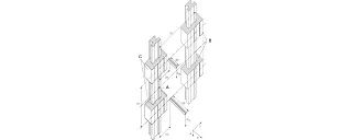
A = Coordinate origin
B = floating bearing
C = Fixed bearing
Calculating the required drive force
Firstly, four calculations must be carried out:


Step 4:
Calculate the maximum bearing load


| Fa: | drive force | [N] |
| Fs: | Mass force | [N] |
| Fy, Fz: | Bearing load in y or z direction | [N] |
| sx, sy, sz: | Distance of the mass force in x-, y- or z-direction | [mm] |
| ay, az: | Distance of the drive force in the y or z direction | [mm] |
| wx: | Distance between the wagons on a rail | [mm] |
| LX: | Size-dependent constant | [mm] |
| Zm: | Size-dependent constant | [mm] |
| Y0: | Size-dependent constant | [mm] |
| b: | Distance between the guide rails | [mm] |
| µ: | coefficient of friction, µ = 0 for static loads, µ = 0.2 for dynamic loads | |
| ZW: | Number of slides per rail |
Step 5:
Check the maximum bearing load of the most heavily loaded bearing with the load calculated in step no. 4
| Order number | Fymax, Fzmax [N] |
|---|---|
| TW-01-15 | 2,000 |
| TW-01-20 | 3700 |
| TW-01-25 | 5,000 |
| TW-01-30 | 7,000 |
Step 6:
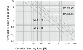
graph to determine the maximum permissible speed for the determined bearing load.
X = centric bearing load [N]
Y = permissible average speed [m/s]
Determination of the maximum permissible speed for the load from step no. 4
Consulting
I look forward to answering your questions

Shipping and consultation
In person:
Monday to Friday from 8:30am - 5.30 pm.
Online:
24h
WhatsApp-Service:
Monday - Friday: 8:30am - 5.30 pm.