Change Language :
Test reports of the bus cables
Discover all our durability test reports for our bus cables here.
Bus cable CFBUS.045
Using the CFBUS in practice
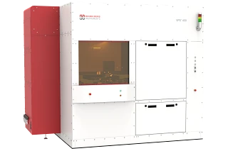
Reliable data transmission, especially in a bus system as versatile as Ethernet, is vital for many systems. In semiconductor production in particular, it is essential to adhere to short cycle times and avoid downtimes, which also presents a challenge for sensitive electronics. The radii and accelerations found here are among the most extreme, so that the TPE outer jacket of the CFBUS.045 can show its full performance here.
Bus cable CFBUS.PUR.049
Using the CFBUS.PUR in practice
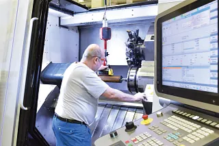
A display on a machine is literally the control centre where every function of a machine tool is set and controlled. These operating units are often supplied with Ethernet cables to enable fast data transfer in real time. It has proven to be a good idea, especially for large systems, to make this control centre mobile and even linearly movable. A reliable cable is now required here in order to be able to reliably map the recurring movements.
Bus cable CFBUS.052
Using the CFBUS in practice
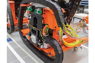
The aim of the test was to determine the service life of the chainflex bus cable in a radius of 100mm with a travel of up to 7 metres. The requirement for this Ethernet cable is to ensure reliable data transmission over the longest possible service life despite constant movement.
The quality requirement in combination with a small bend radius is particularly prevalent in industrial machines and applications that have to process a large amount of data. In addition, small installation spaces are often a major challenge for the durability of the cable.
Bus cable CFBUS.060

Using the CFBUS in practice
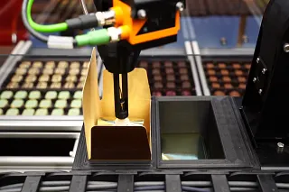
Profinet is a true all-rounder bus, from the automotive industry to machine tool manufacturers, the green cable can be found everywhere. But especially in applications that require many and tight bend radii, such as in vending machinery, it is important that data transmission is guaranteed. Thanks to its TPE jacket, the CFBUS.060 can realise extreme double stroke rates with a very tight bend radius, as this test proves. Thanks to the temperature resistance of -35 to +70°C, even cooled vending machines are no problem and, thanks to the sliding properties of the cable, it can be operated maintenance-free for a long time. For devices in the medical sector, e.g. pharmacy vending machines, it should also be noted that the cable can also be used in cleanrooms thanks to its ISO Class 1 certification.
Bus cable CFBUS.LB.049
Using the CFBUS.LB in practice
The bus cable shown here is frequently used in applications where fast handling is required. Short cycle times and the flexibility of handling systems are very important here. This means that the cables used must be able to withstand the highest demands. One example of this is the food industry. Fast handling robots must combine maximum precision, short cycle times and lightweight.
Bus cable CFROBOT8.045
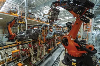
Using the CFROBOT8 in practice
The CFROBOT8.045 cable is very often used in automotive production, e.g. in moving measuring units assembled on the 6th axis of the robot. There they move to inspection points and carry out analyses for quality assurance in production. To do this, the cables that transport the sensitive Ethernet signal are twisted a great deal. For such tasks, 100% reliability on the robot counts.
CFROBOT8.PLUS.045 bus cable
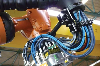
Using the CFROBOT8.PLUS in practice
Camera-based robot applications are often used in industry, e.g. to recognise barcodes or carry out quality assurance. However, this application is also used in television studios. Here, it is particularly important to have an extremely reliable energy and data supply and to be able to carry out very demanding movements.
Bus cable CFSPECIAL.182.045 / Ethernet CAT5e
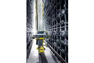
Using the CFSPECIAL.182.045 in practice
Storage and retrieval machines are typical examples of applications in which high tensile strain is exerted on the individual components, as they are used for the automated loading of high-bay warehouses. The bus cable CFSPECIAL.182.045 for Ethernet CAT5e was specially developed for this sector and can withstand the forces due to the aramid braiding in the outer jacket. Therefore, this cable is the safe variant for such and other hanging applications.
Consulting
I look forward to answering your questions

Shipping and consultation
In person:
Monday to Friday from 8:30am - 5.30 pm.
Online:
24h
WhatsApp-Service:
Monday - Friday: 8:30am - 5.30 pm.